Automatic voltage stabilizer for home use is one of UKEO’s products, we are a factory, an integration of manufacturer and trading company, we can offer you the best price, no middlemen take a cut, if you need Automatic voltage stabilizer for home use You are welcome to come to us, we provide OEM&ODM service.
| Requirments / Model | 10000VA | 15000VA | 20000VA | 30000VA | 50000VA | 60000VA | 80000VA | 100KVA | |
| Input | Phase | Three phase | |||||||
| Voltage | 305V-433V AC | ||||||||
| Frequency | 50/6OHz | ||||||||
| Adjusting time | <0.1s(when input voltage has a change of 10%) | ||||||||
| Output | Voltage | 380V士3%AC | |||||||
| Frequency | 50/60Hz | ||||||||
| Loading power factor | 0.8 | ||||||||
Environ -mental | Operating temperature | -5~+40℃ | |||||||
| Storage temperature | -10~+50℃ | ||||||||
| Humidity | 20% to 90% | ||||||||
| Protection | Over Volt. | YES | |||||||
| Overheating | YES | ||||||||
| Over load | YES | ||||||||
| Short Circuit | YES | ||||||||
| Low voltage | YES | ||||||||
| Delay | YES | ||||||||
| Packaging | Net Wt.(KG) | 35 | 43.6 | 69.6 | 80.2 | 98 | 145 | 180 | 256 |
| PCS PER CTN | 1 | ||||||||
| Gross Wt.(KG) | 47.8 | 57.6 | 84.6 | 96.2 | 116 | 165 | 198 | 276 | |
| Product size(mm) | 320*320*775 | 350*350*855 | 425*375*870 | 440*410*906 | 510*420*970 | 550*445*1205 | 600*495*1320 | 600*600*1320 | |
| Package size(mm) | 410*410*900 | 440*400*980 | 515*470*1000 | 510*540*1030 | 600*510*1100 | 680*575*1400 | 730*630*1500 | 730*730*1500 | |

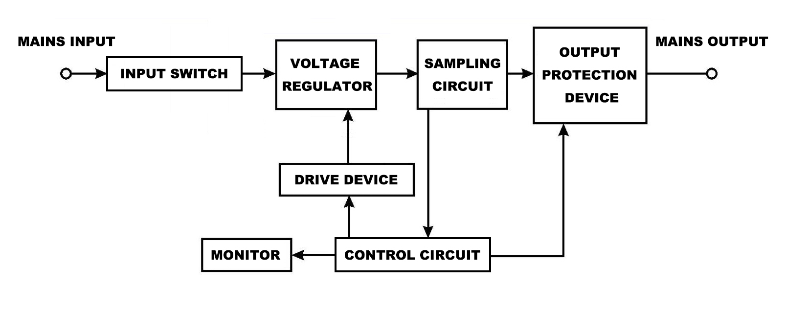
As the input working switch of the voltage stabilizer, the air switch type small circuit breaker with current limiting protection is generally adopted, which can protect the voltage stabilizer and electrical equipment.
It is a device that can regulate the output voltage. It can increase or decrease the output voltage and is the most important part of the voltage regulator.
It detects the output voltage and current of the regulator, and transmits the change of the output voltage to the control circuit.
Since the control electrical signal of the control circuit is weak, it is necessary to use a drive device for power amplification and conversion.
a device that connects and disconnects the output of the voltage stabilizer. Generally, relays, contactors, or fuse are commonly used.
It analyzes the sampled circuit detection model. When the output voltage is too high, it sends a control signal to reduce the voltage to the drive device, and the drive device will drive the voltage regulator to lower the output voltage. When the voltage is low, a control signal for increasing the voltage is sent to the driving device, and the driving device will drive the voltage regulating device to increase the output voltage, so that the output voltage is stabilized to achieve a stable output.
When it is detected that the output voltage or current exceeds the control range of the regulator. The control circuit will control the output protection device to disconnect the output to protect the electrical equipment, and the output protection device is connected to the output under normal conditions, and the electrical equipment can obtain a stable voltage supply.
UKEO Electric is an international enterprise specializing in power distribution equipment such as voltage stabilizers, sockets, lamp holders, power cords, etc. Its main products are: relay type voltage stabilizers, servo type voltage stabilizers, movable sockets, etc. Please add customer service consultation for product price.
There are many types of household voltage stabilizers and protectors on the market, but most of them rely on relays to change the tap of the transformer to adjust the voltage. The disadvantage of this kind of voltage stabilizer is that when the mains power entering the voltage stabilizer changes, it will cause an instant power failure, which will cause the impact of inrush current to the home appliances that are working. The AC servo-type voltage stabilizer can overcome the shortcomings of the above-mentioned voltage stabilizer very well.
The circuit is composed of 2 groups of micro-power consumption control units and 1 group of rectified regulated power supply (specific components and models are shown in Figure 1).
One set is used to reflect the power supply voltage boost control; the other set is used to reflect the power supply voltage drop control.
First, J1 is used to control the forward rotation of the motor and increase the output voltage of the voltage regulator; secondly, J2 is used to control the reverse rotation of the motor and reduce the output voltage of the voltage regulator. At the same time, J1′ is serially connected to the forward rotation loop to prevent the forward rotation phenomenon from occurring during reverse rotation; third, J2′ is serially connected to the reverse rotation circuit to prevent reverse rotation phenomenon from occurring during forward rotation. Connect 2 LEDs in series in 2 groups of controls. The operation of the motor can be observed intuitively. A set of better rectifier and voltage regulator circuits are used to ensure the stability of the circuit. 2 red and green diodes are used to indicate control power.

Before putting into operation, it is necessary to set the action pre-value of 2 groups of control circuits. The action value of the overvoltage control circuit is 230V, and when the output voltage U2 of the voltage regulator changes with the power supply voltage U1 to 230V, J1 pulls in; the action value of the undervoltage control circuit is 210V, and the output voltage U2 of the voltage regulator changes with the power supply voltage U1 to 230V. J2 pulls in at 210V. This ensures that when the output voltage U2 of the voltage regulator is 210-230V, J1 and J2 will not act, and the motor will neither rotate forward nor reverse. Please contact us if you need Automatic voltage stabilizer for home use.
When U2 rises to 230V with the change of U1, the voltage applied to the overvoltage control circuit also rises. At this time, the overvoltage regulation loop is executed, GO1 acts, the red light is on, J1 is pulled in, and its normal The open contact J1 is closed, the motor reverse circuit is turned on, and the carbon brush of the voltage regulator is driven to reverse and slide to reduce the output voltage U2 (at this time, the normally closed contact J1′ is disconnected, and the motor will not rotate forward).
When U2 decreases to 210V with the change of U1, the voltage applied to the undervoltage control circuit also decreases. At this time, the undervoltage regulation loop is executed, G02 acts, the red light is on, J2 is closed, and it is normally open. When the contact J2 is closed, the forward rotation circuit of the motor is turned on, which drives the carbon brush of the voltage regulator to rotate and slide forward, so as to increase the output voltage U2 (at this time, the normally closed contact J2′ is disconnected, and the motor will not reverse).
When U2 changes between 210~230V with U1, G01 and G02 will not act, the red and green lights will not be on, and the motor will stop, which basically ensures that the voltage regulator output U2 is stabilized at 210~ 230V.
In order to prevent the motor from continuing to rotate forward when the power supply voltage is too low, a micro-motion limit switch is connected in series with the J2 normally closed contact circuit, and the switch is installed at the limit position of the carbon brush. When the motor drives the carbon brush to the limit When it is in position, the upper-gear top-opening microswitch installed on the shaft of the voltage regulator forces the motor to stop.
Commissioning in 2 steps with 1 autovoltage regulator:
(1) The control circuit is installed in a control box;
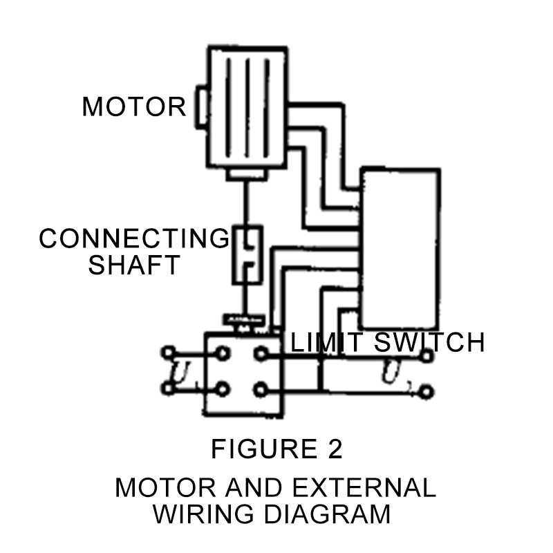
(2) The motor and external wiring are shown in Figure 2, and the selection of components is shown in Table 1;
(3) The control circuit is connected to the output end of the voltage regulator, adjust the voltage regulator to make its output 230V, and then adjust RW1 to make J1 pull in;
(4) Adjust the voltage regulator so that its output is 210V, and then adjust RW2 to make J2 pull in;
(5) Adjust the voltage regulator so that its output is 220V.

Serial number | Name | Model | Serial number | Name | Model |
1 | R1,R2,R3,R7 | 3kΩ | 9 | TB | 220V/18V2-5W |
2 | R4,R5,R6,R8,R9,R10 | 20kΩ | 10 | TY |
|
3 | C7,C8 | 474 | 11 | rectifier block | KBL408G |
4 | C1,C2 | 100μF/50V | 12 | bridge stack | ZL |
5 | C3,C4 | 100μF/25V | 13 | J1,J2 | M1-SH-224L |
6 | C5,C6 | 0.1μF/25V | 14 | op amp | LM324 |
7 | C9 | 2μF/250V | 15 | motor | ND-15 |
8 | C10 | 470μF/25V |
|
|
|
If the voltage is normal and all the equipment in the home can work normally, there is no need to use a voltage stabilizer. If the voltage at home is often abnormal, it is necessary to choose a high-quality voltage stabilizer. When choosing a voltage stabilizer , please choose good quality, it is necessary to choose a voltage stabilizer suitable for your home environment.
UKEO helps you choose an automatic voltage stabilizer for home use.
For the use of the voltage stabilizer, if we are under normal circumstances, the voltage at home is high and low, and some electrical equipment cannot operate normally, the lighting equipment is flickering, the air conditioner is turned on, the external unit makes abnormal noise, etc., most of the reasons for this situation are due to low voltage. So in these cases, after we measure the voltage, if the voltage is lower than 220V, the voltage is too low. When the voltage is at 200V, it exceeds the acceptable voltage range of most of our electrical equipment. At this time, a voltage regulator is required.
UKEO offers the best Automatic voltage stabilizer for home use.
Factory Address:Wuqu Industrial area,Shouning city,Fujian,China
Brand Office Address: No.1780 Wenzhou Av. Lucheng district,
Wenzhou,Zhejiang,China.
Whatsapp: Wechat:

Copyright © 2021 UKEO Design