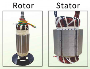
 The main structural parts are the rotating part R and the static part S. And the rotating part is wound around the winding in parallel with the power supply line, and then the winding of the static part is the secondary winding and the load in series.
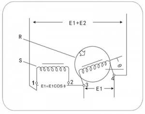
When a certain primary voltage E1 is applied between 3 and 4, and the voltage induced by the secondary winding changes according to the angle φ between the two windings, and then with the change, E2=E1cos φ can change continuously.
In addition, if the connection between 2 and 3 Together, and the terminal voltage between 1 and 4 is equal to E1+E2=E1(1+cos φ). And if the two windings are parallel in the same direction, the terminal voltage between 1 and 4 is the maximum, which is equal to E1+E2.
As for the two windings facing each other at right angles, and the secondary winding has no induced voltage E2 = 0, the terminal voltage is equal to the supply voltage E1, if the rotating part continues to rotate again and φ is greater than 90, and the secondary winding also has an induced voltage, but the induced voltages E2 and E1 Instead, the terminal voltage is equal to the difference between E1 and E2.
From the above, it is known that according to the relative position of the primary and the secondary, and the voltage can be continuously adjusted and changed from the change of the primary magnetic flux when there is a load. And then its advantages lie in its large manufacturing capacity, strong instantaneous overload capability and low failure rate.