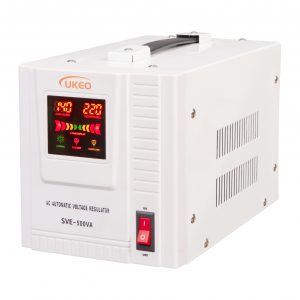
Voltage stabilizer for home – Table type is a stabilizer suitable for home use, but also suitable for various other occasions. Its compact shape and accurate output voltage are important conditions to ensure that it can be used in various occasions. If you need a voltage stabilizer, please contact us through the contact information at the bottom of the page or the chat tool in the lower right corner of the site.
| Requirments / Model | 500VA | 1000VA | 1500VA | 2000VA | 3000VA | 5000VA | 8000VA | 10000VA | |
| Input | Phase | Single phase | |||||||
| Voltage | 70V-260V / 110V-260V / 140V-260V Options | ||||||||
| Frequency | 50/6OHz | ||||||||
| Adjusting time | <0.5s(when input voltage has a change of 10%) | ||||||||
| Output | Voltage | 220V士3%AC | |||||||
| Frequency | 50/60Hz | ||||||||
| Loading power factor | 0.8 | ||||||||
| Environmental | Operating temperature | -5~+40℃ | |||||||
| Storage temperature | -10~+50℃ | ||||||||
| Humidity | 20% to 90% | ||||||||
| Protection | Over Volt. | YES | |||||||
| Overheating | YES | ||||||||
| Over load | YES | ||||||||
| Short Circuit | YES | ||||||||
| Low voltage | YES | ||||||||
| Delay | YES | ||||||||
| Packaging | Net Wt.(KG) | 3.64 | 5.84 | 7.21 | 7.7 | 12.82 | 15.38 | 24.16 | 27.8 |
| PCS PER CTN | 4 | 2 | 1 | ||||||
| Gross Wt.(KG) | 16.56 | 25.6 | 30.26 | 16.59 | 13.9 | 16.96 | 26.1 | 29.78 | |
| Product size(mm) | 252*149*172 | 286*209*202 | 306*209*202 | 370*270*244 | 442*317*264 | ||||
| Package size(mm) | 375*295*430 | 495*335*490 | 495*335*490 | 425*310*305 | 495*360*335 | ||||

As the input working switch of the voltage stabilizer, the air switch type small circuit breaker with current limiting protection is generally adopted, which can protect the voltage stabilizer and electrical equipment.
It is a device that can regulate the output voltage. It can increase or decrease the output voltage and is the most important part of the voltage regulator.
It detects the output voltage and current of the regulator, and transmits the change of the output voltage to the control circuit.
Since the control electrical signal of the control circuit is weak, it is necessary to use a drive device for power amplification and conversion.
a device that connects and disconnects the output of the voltage stabilizer. Generally, relays, contactors, or fuse are commonly used.
It analyzes the sampled circuit detection model. When the output voltage is too high, it sends a control signal to reduce the voltage to the drive device, and the drive device will drive the voltage regulator to lower the output voltage. When the voltage is low, a control signal for increasing the voltage is sent to the driving device, and the driving device will drive the voltage regulating device to increase the output voltage, so that the output voltage is stabilized to achieve a stable output.
When it is detected that the output voltage or current exceeds the control range of the regulator. The control circuit will control the output protection device to disconnect the output to protect the electrical equipment, and the output protection device is connected to the output under normal conditions, and the electrical equipment can obtain a stable voltage supply.
UKEO Electric is an international enterprise specializing in power distribution equipment such as voltage stabilizers, sockets, lamp holders, power cords, etc. Its main products are: relay type voltage stabilizers, servo type voltage stabilizers, movable sockets, etc. Please add customer service consultation for product price.

The word “servo” comes from the Greek word for “slave”. “Servo motor” can be understood as a motor that absolutely obeys the command of the control signal: before the control signal is sent, the rotor is stationary; when the control signal is sent, the rotor rotates immediately; when the control signal disappears, the rotor can stop immediately.
Servo motors are micro motors used as actuators in automatic control devices, and their function is to convert electrical signals into angular displacement or angular velocity of a rotating shaft.
1. Servo mechanism is an automatic control system that enables the output controlled quantities such as the position, orientation, and state of the object to follow any changes in the input target (or given value). The servo mainly relies on pulses for positioning. Basically, it can be understood in this way that when the servo motor receives one pulse, it will rotate the angle corresponding to one pulse to realize displacement.
Because the servo motor itself has the function of sending out pulses, each time the servo motor rotates an angle, it will send out a corresponding number of pulses, which echoes the pulses received by the servo motor, or is called a closed loop. In this way, the system will know How many pulses are sent to the servo motor, and how many pulses are received at the same time, so that the rotation of the motor can be precisely controlled, so as to achieve precise positioning, which can reach 0.001mm.
1. DC servo motors are divided into brushed and brushless motors.
Brushed motors have low cost, simple structure, large starting torque, wide speed regulation range, easy control, and require maintenance, but maintenance is inconvenient (carbon brush replacement), generates electromagnetic interference, and has environmental requirements. Therefore, it can be used in cost-sensitive general industrial and civil applications.
The brushless motor is small in size, light in weight, large in output, fast in response, high in speed, small in inertia, smooth in rotation and stable in torque. The control is complex, and it is easy to realize intelligentization. Its electronic commutation mode is flexible, and it can be square wave commutation or sine wave commutation. The motor is maintenance-free, has high efficiency, low operating temperature, small electromagnetic radiation, long life, and can be used in various environments.
2. The AC servo motor is also a brushless motor, which is divided into synchronous and asynchronous motors. At present, synchronous motors are generally used in motion control. It has a large power range and can achieve a large power. High inertia, low maximum rotational speed, and decreases rapidly with increasing power. Therefore, it is suitable for applications that operate smoothly at low speeds.
3. The rotor inside the servo motor is a permanent magnet. The U/V/W three-phase electricity controlled by the driver forms an electromagnetic field. The rotor rotates under the action of this magnetic field. At the same time, the encoder that comes with the motor feeds back the signal to the driver, and the driver according to the feedback value Compared with the target value, the angle of rotation of the rotor is adjusted. The accuracy of the servo motor is determined by the accuracy (number of lines) of the encoder.
AC servo is better, because it is sine wave control, and the torque ripple is small. DC servos are trapezoidal waves. But DC servo is simpler and cheaper.
Factory Address:Wuqu Industrial area,Shouning city,Fujian,China
Brand Office Address: No.1780 Wenzhou Av. Lucheng district,
Wenzhou,Zhejiang,China.
Whatsapp: Wechat:

Copyright © 2021 UKEO Design